
Week 6: Sensor Input and Calibration
Assignment Overview
This week’s tasks involved creating and configuring sensors to measure physical quantities using a microcontroller. The focus was on avoiding the delay() function and utilizing timers, as well as employing C++ class structures.
Capacitive Sensor Design
Setup: I used two pieces of copper separated by a piece of velostat for the capacitive sensor. This setup is shown in the image below:
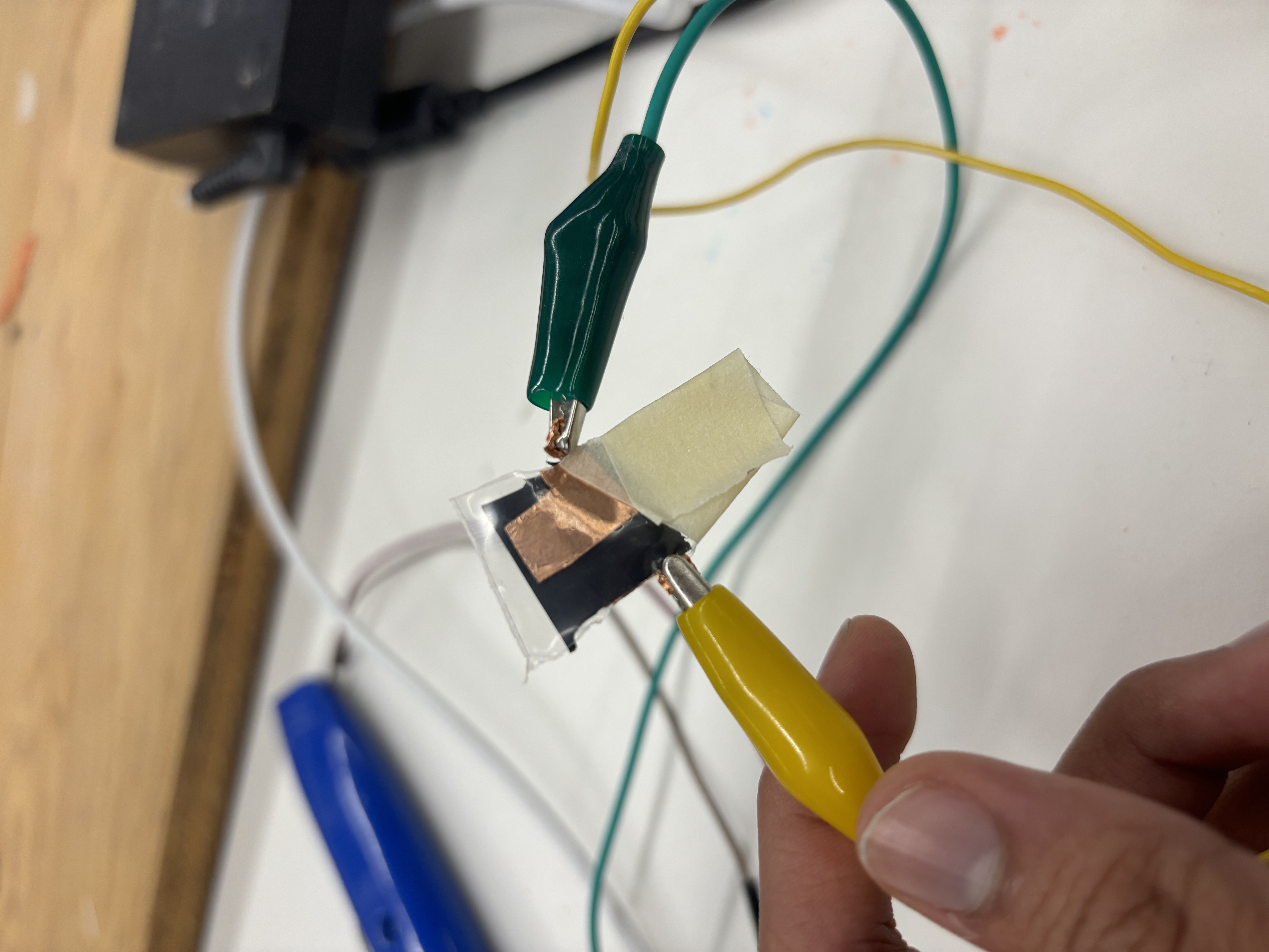
Functionality: I connected one side to a pin for digital writing and read the difference from the other pin, similar to tx-rx sensing as outlined here.
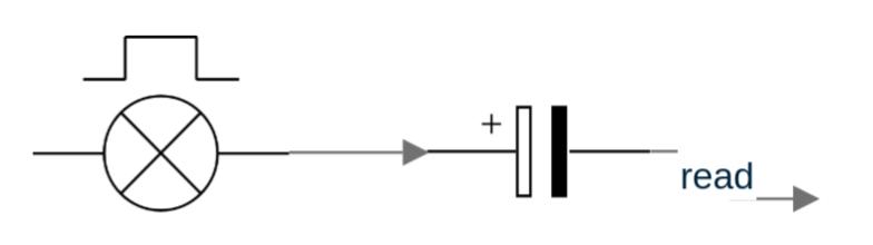
Schematic: The schematic for the sensor setup is shown below:
Calibration: I calibrated the sensor using the number of nuts as a unit of measurement, with the experiment setup shown below where essentially I used number of nuts as the weight:
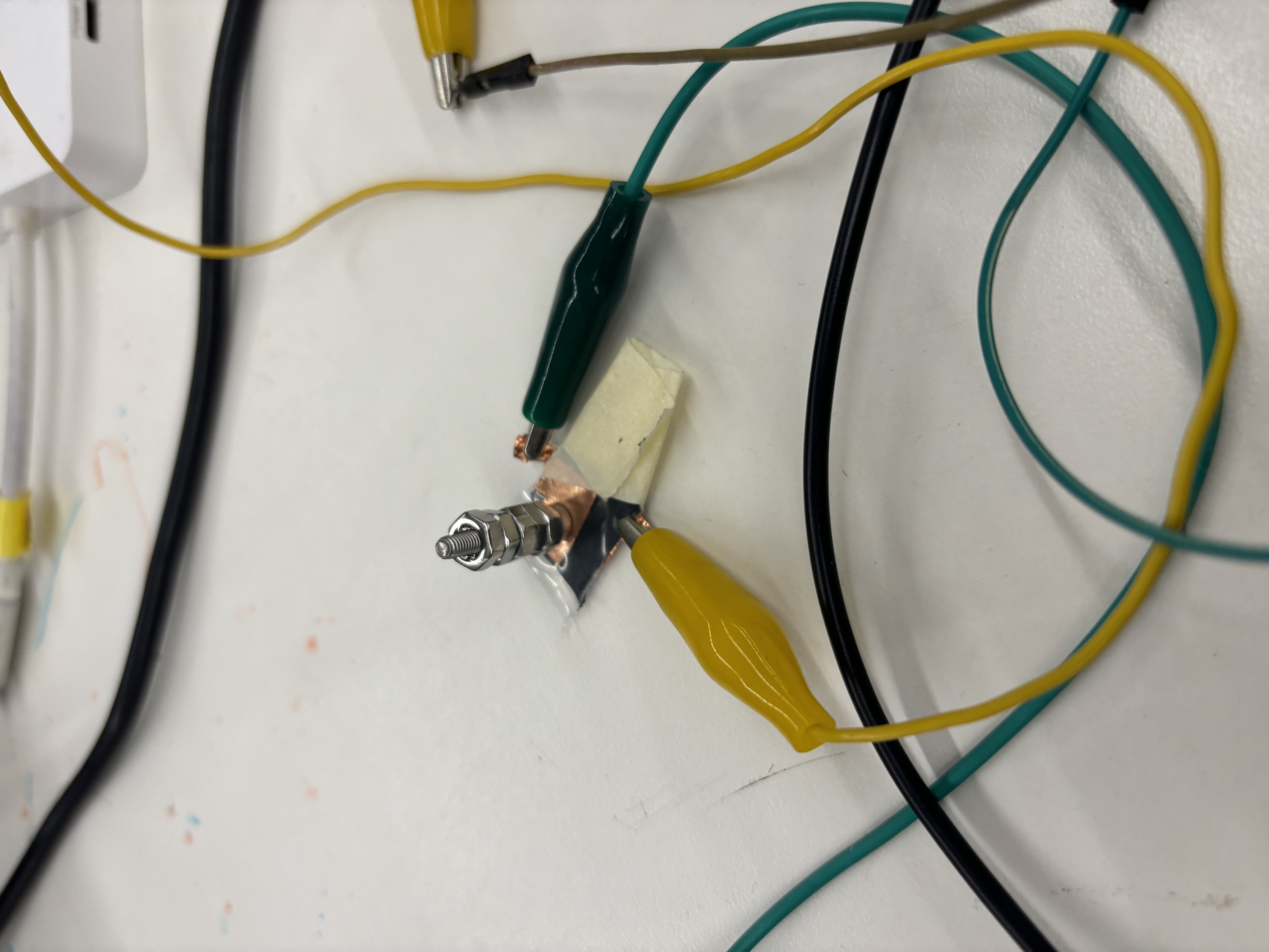
The results indicate an exponential decrease in readings with larger weights, aligning with the expected behavior of tx-rx sensors because the difference between the input signal and output signal decreases as the pieces of copper become closer together.
Number of M2 Washers Reading 0 47000 1 46000 2 45000 3 43000 4 32000 5 17000
Thermistor Setup
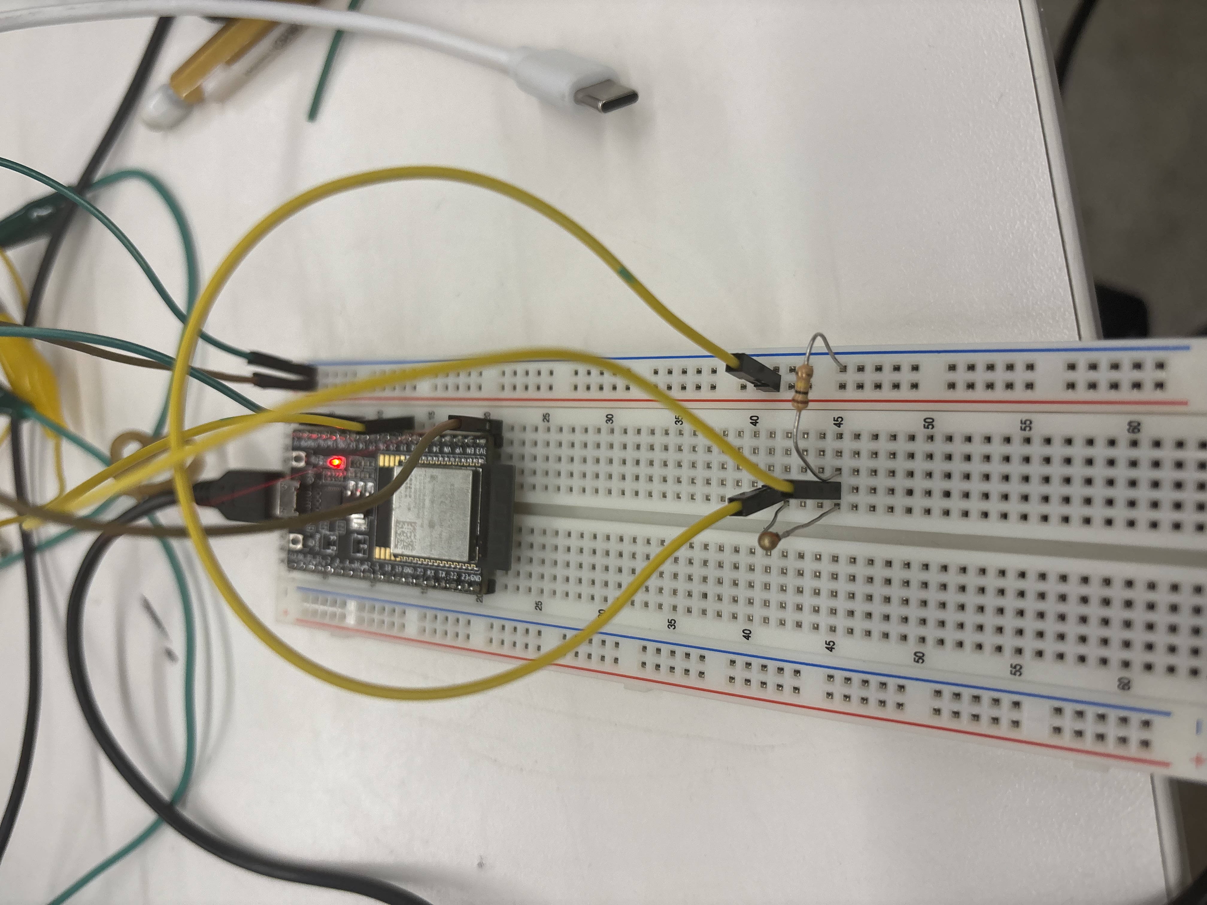
Circuit: I followed the wiring instructions from class for the thermistor setup. The circuit is depicted in the image below:
CNC Preparation
- CAD Files: Prepared CAD files for CNC week, considering both 2D DXF files for routing sheet material and 3D STL files for milling 2.5D shapes.